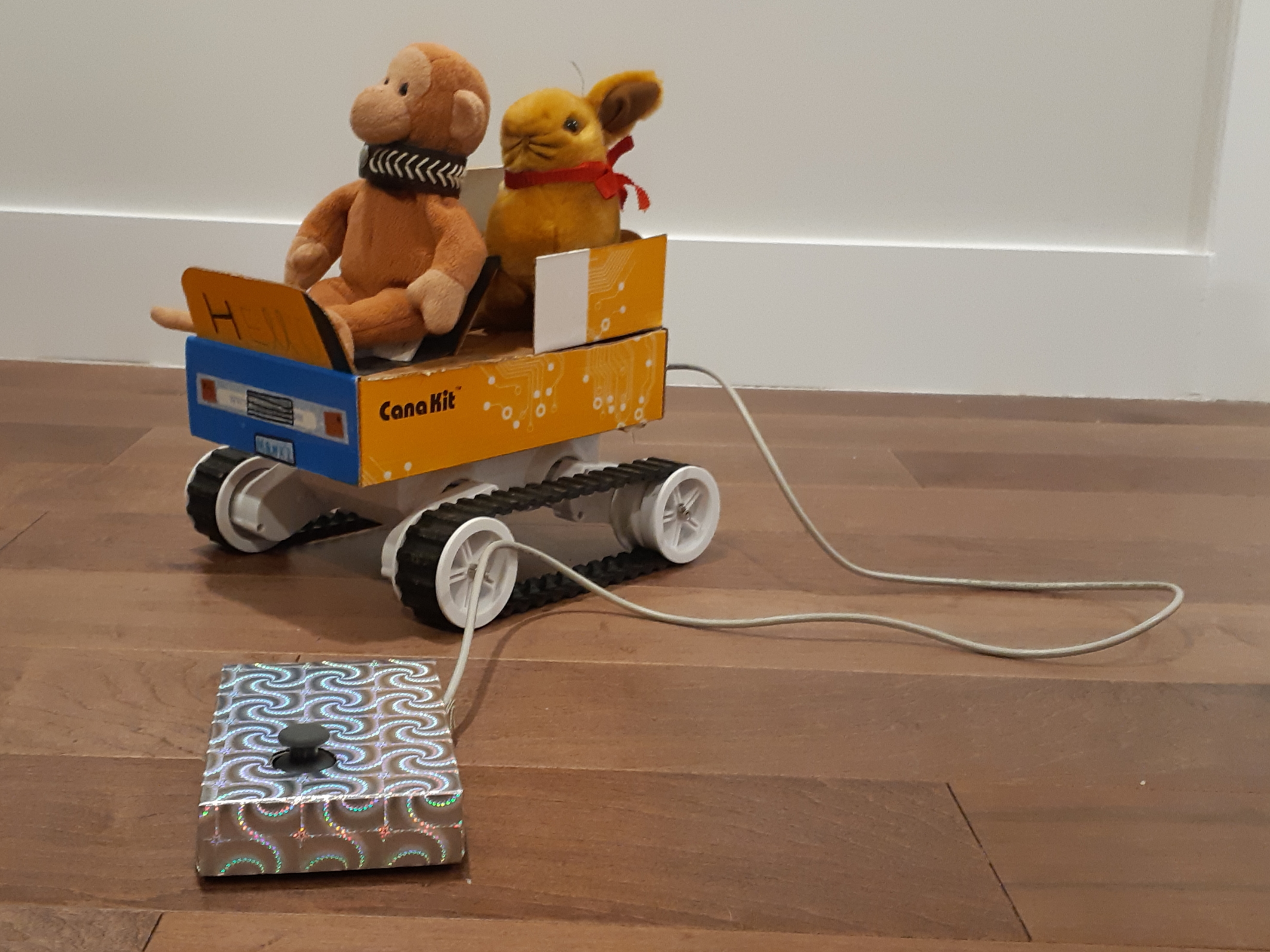
The best projects are ones where you manage to find everything on-hand and no waiting for deliveries or going out to get extra material. Thus is the case with Monkey Tank. My nine-year old has a small stuffed monkey (named, you guessed it: “Monkey”) and wanted to build a little remote control car for it. Kids being kids, she does not have a lot of patience and also aren’t giant perfectionists, so I wanted something quick but fun.
At home, I had a Rover S Robot Chassis that I thought I could do something at the cottage with, plus other miscellaneous parts (joystick, Arduino Uno, motor shield), Since I source most of my parts from Creatron, that’s where you are seeing most of the links.
The parts list is as follows:
- Thumb joystick similar to this one
- Rover S Robot Chassis
- Arduino Uno
- Ardumoto motor shield
- Simple on/off switch
- Wires, AA batteries, etc. For the joystick wire, I had a bunch of old Ethernet cables lying around. It had one less wire than I needed (for the button) but that’s for a later post.

Any other tutorial I have seen of the chassis has really messy wiring, so no apologies as I follow that grand tradition. I did, however label the connectors (RF for “right front”, LF for “left front, and so on).

Coming to the rescue is a Fritzing diagram of the clean circuit. I paired each side (e.g. the left side together on one output, the right side together on the other output).

I found a sparkly box that probably had costume jewelry in it at some point. I wanted most of the body and casing to just be out of cardboard to be easy to cut and customize.

For the body, we had an old Cana Kit box from a Raspberry Pi delivery, which turns out it was just the right size.

Finally below is the simple code. Thanks to past contributors and documentation, this was a fun project!
    /* Ardumoto and Rover S chassis sketch
  by: Joseph Lalonde
  website: https://zenbot.ca
  twitter: https://twitter.com/jpindi
  date: May 17, 2020
  license: Public domain. Please use, reuse, and modify this
  sketch.

  Special thanks to:
  Jim Lindblom, originally created November 8, 2013

  Adapted to v20 hardware by: Marshall Taylor, March 31, 2017

 With ardumoto, do NOT use pins 12, 3, 13, 11
 */

int JoyHorz = A0;
int JoyVert = A1;

int JoyPosVert = 512;
int JoyPosHorz = 512;
// Clockwise and counter-clockwise definitions.
// Depending on how you wired your motors,
// you may need to swap.

#define FORWARD  0
#define REVERSE 1

// Motor definitions to make life easier:
#define MOTOR_A 0
#define MOTOR_B 1

// Pin Assignments
#define DIRA 12 // Direction control for motor A
#define PWMA 3 // PWM control (speed) for motor A
#define DIRB 13 // Direction control for motor B
#define PWMB 11 // PWM control (speed) for motor B

char data[100];

void setup()
{
  Serial.begin(9600); //I had the output to serial for troubleshooting.
  setupArdumoto(); // Set all pins as outputs
  stopArdumoto(MOTOR_A); //set to zero to start off
  stopArdumoto(MOTOR_B);

void loop()
{
  JoyPosVert = analogRead(JoyVert);
  JoyPosHorz = analogRead(JoyHorz);
  if (JoyPosVert < 200 || JoyPosVert > 800){
    // this 200 and 800 I had to play with trial and error
    // to get the right amount.
  if (JoyPosVert < 200){
  // this is in REVERSE
    driveArdumoto(MOTOR_A, REVERSE, 255);
    driveArdumoto(MOTOR_B, REVERSE, 255);
  }
  else if (JoyPosVert > 800) {

    driveArdumoto(MOTOR_A, FORWARD, 255);
    driveArdumoto(MOTOR_B, FORWARD, 255);

  } // end of if JoyPosVert
  } else if (JoyPosVert > 300 || JoyPosVert < 900) {
   if (JoyPosHorz > 900) { ////turn right

    driveArdumoto(MOTOR_A, REVERSE, 75); ////topsy turvy world!
    driveArdumoto(MOTOR_B, REVERSE, 255);
  }
  else if (JoyPosHorz < 200) { ////turn left

    driveArdumoto(MOTOR_A, REVERSE, 255);
    driveArdumoto(MOTOR_B, REVERSE, 75);
  }
  else {  ///do nothing
    stopArdumoto(MOTOR_B);
    stopArdumoto(MOTOR_A);
  }
  }else {  ///do nothing
    stopArdumoto(MOTOR_B);
    stopArdumoto(MOTOR_A);
  }
  sprintf(data, "Vertical input is: %d and Horizontal input is %d;", JoyPosVert, JoyPosHorz);
  //sprintf(data, "Sensor value of A3 is: %d and mapped is %d", bright, br_map);
  Serial.println(data);
delay(100);
} //end of void loop

// driveArdumoto drives 'motor' in 'dir' direction at 'spd' speed
void driveArdumoto(byte motor, byte dir, byte spd)
{
  if (motor == MOTOR_A)
  {
    digitalWrite(DIRA, dir);
    analogWrite(PWMA, spd);
  }
  else if (motor == MOTOR_B)
  {
    digitalWrite(DIRB, dir);
    analogWrite(PWMB, spd);
  }
}

// stopArdumoto makes a motor stop
void stopArdumoto(byte motor)
{
  driveArdumoto(motor, 0, 0);
}

// setupArdumoto  setup the Ardumoto Shield pins
// initialize all pins
void setupArdumoto()
{
  // All pins should be setup as outputs:
  pinMode(PWMA, OUTPUT);
  pinMode(PWMB, OUTPUT);
  pinMode(DIRA, OUTPUT);
  pinMode(DIRB, OUTPUT);

  // Initialize all pins as low:
  digitalWrite(PWMA, LOW);
  digitalWrite(PWMB, LOW);
  digitalWrite(DIRA, LOW);
  digitalWrite(DIRB, LOW);
}