Category: Maker

  • Bluetooth RGB lights using ESP32

    Car lights talking to each other via bluetooth

    Some time ago, one of my kids came home with a couple of discarded truck lights they’d found. They’re the kind that go on the rear of a vehicle, with space for three bulbs each. They were in surprisingly good shape, so we started wondering: what if we put multicolour lights inside them and turned them into something new?


    Before I got too far, I was given a short list of requirements. The lights needed to hang on the wall. They needed to talk to each other wirelessly. They had to show multiple colours. And, finally, could they run on batteries so we wouldn’t have cables dangling everywhere? No pressure.


    Saying I went down a few dead ends would be putting it mildly. My first attempt involved a separate remote control and Arduino WiFi MKR 1010 boards, but I quickly ran into trouble. The boards were finicky about staying connected to Wi-Fi, performance was inconsistent, and the whole setup felt more complicated than it needed to be. Eventually, I switched to ESP32 boards using Bluetooth and moved the controls directly into one of the lights instead of a separate controller. The ESP32s just worked. In hindsight, if I’d started there, I probably could have avoided a lot of detours.


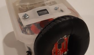
    Of course, car lights aren’t exactly designed to hold a collection of hobbyist electronics. To make everything fit, I ended up 3D-printing several small boxes and covers, attaching them with bolts or Velcro. I deliberately avoided drilling new holes in the original lights, just in case we ever wanted to take the whole thing apart and sell them later.

    Electronic components

    • Common anode RGB LED – There was no reason for using a common anode LED, it wasn’t specified on the Amazon order and it works just as well.
    • ESP32 – as I mentioned earlier, I had tried an Arduino WIFI MKR 1010. As well, I had also tried a Raspberry Pi Pico and I found the ESP32 were more stable and “just worked” for what I needed. I’ll probably use both the Arduino and the Pico for other projects, instead.
    • Buck converter maybe this is overkill but I could pair this with more batteries and get good-enough voltage control.
    • Slide switches – potentiometers would have been more fine-grained, but switches are fine fairly straightforward.
    • Diode – I use this in case I am plugging in my ESP32 to change the code and don’t feel like unplugging the main power. It just does its job, which is to keep the current flowing in the right direction.

    Circuit Diagrams

    I have two diagrams, one is the “sender” of the signal and has three slide switches. The switches turn the colours one and off. The other is the bluetooth “receiver” which does not have any switches but is otherwise the same.

    Wiring diagram of the sender.

    For the 9V battery, I used 6 AA batteries. I really wanted to ensure all the electronics were powered, properly and brought the voltage down using the buck converter.

    Wiring diagram of the receiver. It is mostly the same except there are no slide switches.
    Wiring of receiver module.

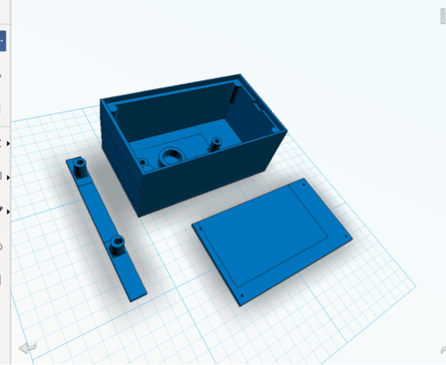
    3D printed components

    The prints aren’t complicated, where the only thing that took any special calculation was a little trigonometry to get some of the angles for the back correct. Getting to use that was nice because I had just been tutoring my oldest in math and now I was able to use it in a “real world” situation. 

    The stl files can be reached via this link on Google Drive https://drive.google.com/file/d/1Uyve7hnl4fjpOUiTSy3FAjQ02FXD4fiL/view?usp=sharing

    Back of lights 3D printed. The square hole is for hanging on the wall.

    Code

    This is the code for the ESP32 that sends commands to the receiving module. Full disclosure is ChatGPT helped troubleshoot this when I got stuck.

    #include <BLEDevice.h>
    #include <BLEUtils.h>
    #include <BLEScan.h>
    #include <BLEClient.h>
    #include <BLERemoteService.h>
    #include <BLERemoteCharacteristic.h>
    #include <Arduino.h>
    #include "driver/ledc.h"
    #include <string>
    
    ///----set the switches
    #define bluePin 4
    #define greenPin 16
    #define redPin 15
    int redState;
    int blueState;
    int greenState;
    
    //------set the LED pins
    const int ledPin1 = 17; //red
    const int ledPin2 = 23; //green
    const int ledPin3 = 22; //blue
    const int ledChannel1 = 0;
    const int ledChannel2 = 1;
    const int ledChannel3 = 2;
    const int freq = 5000;
    const int resolution = 8;
    
    //-------set calculated variables
    int rset;
    int bset;
    int gset;
    
    static BLEAddress *pServerAddress;  // Peripheral BLE address
    static boolean doConnect = false;
    static boolean connected = false;
    static BLERemoteCharacteristic* pRemoteCharacteristic;
    ///the following is for the button
    String sendthing = "1";
    int buttonState = 0;   
    ///end of button thing
    #define SERVICE_UUID        "12345678-1234-1234-1234-1234567890ab"  // Replace with your service UUID
    #define CHARACTERISTIC_UUID "abcdefab-1234-5678-1234-abcdefabcdef"  // Replace with your characteristic UUID
    
    // Callback to handle discovered peripherals during scan
    class MyAdvertisedDeviceCallbacks: public BLEAdvertisedDeviceCallbacks {
        void onResult(BLEAdvertisedDevice advertisedDevice) {
            Serial.print("Found device: ");
            Serial.println(advertisedDevice.toString().c_str());
    
            // If device has the service UUID we want
            if (advertisedDevice.haveServiceUUID() && advertisedDevice.isAdvertisingService(BLEUUID(SERVICE_UUID))) {
                advertisedDevice.getScan()->stop();  // stop scanning
                pServerAddress = new BLEAddress(advertisedDevice.getAddress());
                doConnect = true;                     // flag to connect in loop
                Serial.println("Found target device! Will connect...");
            }
        }
    };
    
    // Connect to peripheral and discover service/characteristic
    bool connectToServer(BLEAddress pAddress) {
        Serial.print("Connecting to ");
        Serial.println(pAddress.toString().c_str());
    
        BLEClient*  pClient  = BLEDevice::createClient();
        Serial.println(" - Created client");
    
        if (!pClient->connect(pAddress)) {
            Serial.println("Failed to connect.");
            return false;
        }
        Serial.println(" - Connected to server");
    
        BLERemoteService* pRemoteService = pClient->getService(SERVICE_UUID);
        if (pRemoteService == nullptr) {
            Serial.println("Failed to find service.");
            pClient->disconnect();
            return false;
        }
        Serial.println(" - Found service");
    
        pRemoteCharacteristic = pRemoteService->getCharacteristic(CHARACTERISTIC_UUID);
        if (pRemoteCharacteristic == nullptr) {
            Serial.println("Failed to find characteristic.");
            pClient->disconnect();
            return false;
        }
        Serial.println(" - Found characteristic");
    
        connected = true;
        return true;
    }
    
    void setup() {
        Serial.begin(115200);
        Serial.print("sending[0] is :");
        Serial.println(sendthing[0]);
      //----these are the on-off switches
      pinMode(redPin, INPUT_PULLUP);
      pinMode(bluePin, INPUT_PULLUP);
      pinMode(greenPin, INPUT_PULLUP);
    
      // Set up PWM channels
      ledcSetup(ledChannel1, freq, resolution);
      ledcSetup(ledChannel2, freq, resolution);
      ledcSetup(ledChannel3, freq, resolution);
    
      // Attach LED pins
      ledcAttachPin(ledPin1, ledChannel1);
      ledcAttachPin(ledPin2, ledChannel2);
      ledcAttachPin(ledPin3, ledChannel3);
    
      // Force the duty to zero - the LEDs are Anode, meaning the 'high' is 'low'
      ledcWrite(ledChannel1, 255);
      ledcWrite(ledChannel2, 255);
      ledcWrite(ledChannel3, 255);
        
        Serial.println("Starting ESP32 BLE Client...");
    
        BLEDevice::init("ESP32_Client");
    
        BLEScan* pBLEScan = BLEDevice::getScan();
        pBLEScan->setAdvertisedDeviceCallbacks(new MyAdvertisedDeviceCallbacks());
        pBLEScan->setActiveScan(true);
        pBLEScan->start(10, false); // scan for 10 seconds
    }
    
    void loop() {
        if (doConnect) {
            if (connectToServer(*pServerAddress)) {
                Serial.println("We are now connected to the BLE Server.");
            } else {
                Serial.println("Failed to connect to server.");
            }
            doConnect = false;
        }
    
        if (connected) {
            if (pRemoteCharacteristic->canRead()) {
              //  String value = pRemoteCharacteristic->readValue();  // Arduino String
                String value = String(pRemoteCharacteristic->readValue().c_str()); // correct for ESP32 BLE Arduino
        Serial.print("Characteristic value: ");
        Serial.println(value.c_str());  // can print Arduino String directly
            }
    
            // Example: write a value
            if (pRemoteCharacteristic->canWrite()) {
                pRemoteCharacteristic->writeValue(sendthing[0]);
                Serial.print("I sent ");
                Serial.println(sendthing[0]);
            }
    
            delay(300);  // wait 0.5 seconds before next read/write
        }
        // put your main code here, to run repeatedly:
      redState = digitalRead(redPin);
      blueState = digitalRead(bluePin);
      greenState = digitalRead(greenPin);
      Serial.print("Red state is: ");
      Serial.print(redState);
      Serial.print(" and Blue state is: ");
      Serial.print(blueState);
      Serial.print(" and Green state is: ");
      Serial.print(greenState);
      Serial.print(" and the sendthing is: ");
      Serial.println(sendthing);
      //all the different possiblities
      if(redState == LOW && greenState == LOW && blueState == LOW){
        sendthing = "1";
      }
      else if(redState == HIGH && greenState == LOW && blueState == LOW){
        sendthing = "2"; //red
      }
      else if(redState == HIGH && greenState == HIGH && blueState == LOW){
        sendthing = "3"; 
      }
      else if(redState == HIGH && greenState == HIGH && blueState == HIGH){
        sendthing = "4";
      }
      else if(redState == LOW && greenState == HIGH && blueState == HIGH){
        sendthing = "5";
      }
      else if(redState == LOW && greenState == LOW && blueState == HIGH){
        sendthing = "6";
      }
      else if(redState == HIGH && greenState == LOW && blueState == HIGH){
        sendthing = "7";
      }
      else if(redState == LOW && greenState == HIGH && blueState == LOW){
        sendthing = "8";
      }
        for (int duty = 0; duty <= 255; duty++) {
          redState == LOW ? rset = 255 : rset = duty ;
          greenState == LOW ? gset = 255 : gset = duty ;
          blueState == LOW ? bset = 255 : bset = duty ;
          ledcWrite(ledChannel1, rset);
          ledcWrite(ledChannel2, gset);
          ledcWrite(ledChannel3, bset);
          delay(30);
        }
      for (int duty = 255; duty >= 0; duty--) {
          redState == LOW ? rset = 255 : rset = duty ;
          greenState == LOW ? gset = 255 : gset = duty ;
          blueState == LOW ? bset = 255 : bset = duty ;
          ledcWrite(ledChannel1, rset);
          ledcWrite(ledChannel2, gset);
          ledcWrite(ledChannel3, bset);
          delay(30);
        }
    }

    The following is the receiver code on the module with no switches.

    #include <BLEDevice.h>
    #include <BLEServer.h>
    #include <BLEUtils.h>
    #include <BLE2902.h>
    #include <string>
    #include <Arduino.h>
    #include "driver/ledc.h" 
    
    // UUIDs (use random unique ones if you want)
    #define SERVICE_UUID        "12345678-1234-1234-1234-1234567890ab"
    #define CHARACTERISTIC_UUID "abcdefab-1234-5678-1234-abcdefabcdef"
    
    //------set the LED pins
    const int ledPin1 = 22; //red
    const int ledPin2 = 23; //green
    const int ledPin3 = 17; //blue
    const int ledChannel1 = 0;
    const int ledChannel2 = 1;
    const int ledChannel3 = 2;
    const int freq = 5000;
    const int resolution = 8;
    int rset;
    int bset;
    int gset;
    String value;
    #define LED_1 4
    #define LED_2 5
    int theglobal = 4;
    int usethis = 4;
    BLECharacteristic *commandCharacteristic;
    
    class CommandCallback : public BLECharacteristicCallbacks {
      void onWrite(BLECharacteristic *pCharacteristic) {
        value = String(pCharacteristic->getValue().c_str()); // correct for ESP32 BLE Arduino
        Serial.print("the value is: ");
        Serial.println(value);
        if (value.length() > 0) {
          Serial.print("Received command: ");
         // Serial.println(value.c_str());
            Serial.println(value);
          // Example: turn LED on/off with "ON"/"OFF"
          if (value == "1") {
            // everything off
            rset = 255;
            gset = 255;
            bset = 255;
          } else if (value == "2") {
            // red
            rset = 1;
            gset = 255;
            bset = 255;
          
          } else if (value == "3") {
            // red and green
            rset = 1;
            gset = 1;
            bset = 255;
          
          } else if (value == "4") {
            // white
            rset = 1;
            gset = 1;
            bset = 1;
          
          } else if (value == "5") {
            // yellow
            rset = 255;
            gset = 1;
            bset = 1;
          
          } else if (value == "6") {
            // blue
            rset = 255;
            gset = 255;
            bset = 1;
          
          } else if (value == "7") {
            // purple
            rset = 1;
            gset = 255;
            bset = 1;
          
          } else if (value == "8") {
            // all gree
            rset = 255;
            gset = 1;
            bset = 255;
          }
          // Example: accept "R,G,B" (basic parse for PWM LED strip)
          else {
            /// not sure so just turn everyhing on
            rset = 1;
            gset = 1;
            bset = 1;
          }
        }
      }
    };
    
    void setup() {
      Serial.begin(115200);
        // Set up PWM channels
      ledcSetup(ledChannel1, freq, resolution);
      ledcSetup(ledChannel2, freq, resolution);
      ledcSetup(ledChannel3, freq, resolution);
    
      // Attach LED pins
      ledcAttachPin(ledPin1, ledChannel1);
      ledcAttachPin(ledPin2, ledChannel2);
      ledcAttachPin(ledPin3, ledChannel3);
    
      // Force the duty to zero - the LEDs are Anode, meaning the 'high' is 'low'
      ledcWrite(ledChannel1, 255);
      ledcWrite(ledChannel2, 255);
      ledcWrite(ledChannel3, 255);
    
      BLEDevice::init("ReceiverESP32");  // BLE device name
      BLEServer *pServer = BLEDevice::createServer();
    
      BLEService *pService = pServer->createService(SERVICE_UUID);
    
      commandCharacteristic = pService->createCharacteristic(
        CHARACTERISTIC_UUID,
        BLECharacteristic::PROPERTY_WRITE |
        BLECharacteristic::PROPERTY_READ
      );
    
      commandCharacteristic->setCallbacks(new CommandCallback());
      commandCharacteristic->setValue("Waiting...");
    
      pService->start();
    
      BLEAdvertising *pAdvertising = BLEDevice::getAdvertising();
      pAdvertising->addServiceUUID(SERVICE_UUID);
      BLEDevice::startAdvertising();
    
      Serial.println("Peripheral ready, advertising as 'ReceiverESP32'. With new code!");
    }
    
    void loop() {
        
            
            int rval;
            int bval;
            int gval;
            
        for (int duty = 0; duty <= 255; duty++) {
          rval = max(duty, rset) ;
          bval = max(duty, bset) ;
          gval = max(duty, gset) ;
          ledcWrite(ledChannel1, rval);
          ledcWrite(ledChannel2, gval);
          ledcWrite(ledChannel3, bval);
          Serial.print("the rval is :");
            Serial.print(rval);
            Serial.print(" and the gval is :");
            Serial.print(gval);
            Serial.print(" and the bval is :");
            Serial.print(bval);
            Serial.print(" and the duty is: ");
            Serial.println(duty);
          delay(30);
        }
        delay(30);
      for (int duty = 255; duty >= 0; duty--) {
          rval = max(duty, rset) ;
          bval = max(duty, bset) ;
          gval = max(duty, gset) ;
          ledcWrite(ledChannel1, rval);
          ledcWrite(ledChannel2, gval);
          ledcWrite(ledChannel3, bval);
          Serial.print("the rval is :");
            Serial.print(rval);
            Serial.print(" and the gval is :");
            Serial.print(gval);
            Serial.print(" and the bval is :");
            Serial.print(bval);
            Serial.print(" and the duty is: ");
            Serial.println(duty);
          delay(30);
        }
    }

  • Sound Detector with Microview

    Sound Detector with Microview

    I built this because our new home has a number of pinging ducts and I wanted to get to the bottom of it. So I decided to build something that could ‘hear’ through walls and display the number on a screen. In theory, this should allow me to pinpoint exactly where sounds might be located.

    I had a few components at my fingertips, one of them being the Sparkfun Microview which I might have even obtained way back when they had their Kickstarter campaign. I had built a pretty sweet magnet detector with them, so a sound detector should be relatively the same level of difficulty.

    Image of Sound Detector from top and side
    Sound Detector built with SparkFun components,

    I ordered the Sparkfun sound detector and hooked up all the components (the code below has some notes around that). Because reading the slider numbers were kind of tricky, I created a delay for displaying the current sound level. More useful is the “max” sound which shows quick peaks. In order to reset the maximum sound, I just installed a power button.

    /* Code from Sparkfun sound detector and Microview hookup guide
     * Connections:
     * The Sound Detector is connected to the Microview as follows:
     * (Sound Detector -> Arduino pin)
     * GND ? GND
     * VCC ? 5V
     * Gate ? Pin 1
     * Envelope ? A0
     * 
     * Additional library requirements: none, except Microview
     */
    #include <MicroView.h>
    MicroViewWidget *widget_max, *widget_snd; //declares a widget class which is the slider
    
    //sound variables
    int snd = 0; //this is the read of the sound
    int snd_max = 0; /// this is useful in case of fast, sudden ticks
    
    /// inputs to Microview
    #define PIN_ANALOG_IN A0
    #define PIN_GATE_IN 1 // different than sample code https://learn.sparkfun.com/tutorials/sound-detector-hookup-guide
    
    int counter = 0; ///use this to create a display in reading. why not use delay() function ? Because you want to update 'snd_max' as much as possible
    
    void setup()
    {
      Serial.begin(9600); // I only kept this for troubleshooting
      Serial.println("Initialized"); // again, not really needed
      uView.begin();
      uView.clear(PAGE);
      widget_snd = new MicroViewSlider(0,5,0,1024, WIDGETSTYLE1);//15, 0 is the location, 0, 255 is the slider number
      widget_max = new MicroViewSlider(0,30,0,1024, WIDGETSTYLE1+WIDGETNOVALUE);//50, 0 is the location, 0, 255 is the slider number
    // I have the WIDGETNOVALUE because I have special max text with labels (see further down)
    }
    
    void loop()
    {
      snd = analogRead(PIN_ANALOG_IN);
      counter++ ; ///once this gets up to a certain amount, then update the main slider viz
      Serial.println(counter);
      if(counter >= 90){
          widget_snd->setValue(snd);  //top slider
          counter = 0; // reset counter
      }
      // this next section sets the sound max (bottom) slider
      if(snd > snd_max){snd_max = snd;}
      widget_max->setValue(snd_max);
      // this next section is just to make sure what is max and what is not is visible
      uView.setCursor(10,40);
      char max_text[10];
      sprintf(max_text,"max: %d", snd_max);
      uView.print(max_text);
      uView.display();
      delay(10);
    }

    The assembly used a headphone cover in order to insulate against outside sounds and I could then hold it up against a wall/floor/ceiling. I didn’t have a nice project box that let me look inside, so I used an old plastic box that used to hold nails in it. The advantage is the plastic is soft enough to cut or drill easily and is the right size. It also felt pretty DIY punk rock.

    Image of top view of sound detector
    Sound Detector seen from the top

    Some minor headaches is that the Microview doesn’t have the pin numbers on it, probably for aesthetic reasons. So you keep having to refer to a diagram, which I printed up an posted on a wall. For troubleshooting, you have to disconnect the whole thing and then reconnect it. Because of that, I would say that Microview is great, but not the first hobby micro-controller you ever want to use. I think they are so cute and otherwise easy to use, though, that I feel like the challenges are worth it.

  • Monkey Tank

    Monkey Tank

    The best projects are ones where you manage to find everything on-hand and no waiting for deliveries or going out to get extra material. Thus is the case with Monkey Tank. My nine-year old has a small stuffed monkey (named, you guessed it: “Monkey”) and wanted to build a little remote control car for it. Kids being kids, she does not have a lot of patience and also aren’t giant perfectionists, so I wanted something quick but fun.

    At home, I had a Rover S Robot Chassis that I thought I could do something at the cottage with, plus other miscellaneous parts (joystick, Arduino Uno, motor shield), Since I source most of my parts from Creatron, that’s where you are seeing most of the links.

    The parts list is as follows:

    View of tank opened to show wiring
    Overview of tank

    Any other tutorial I have seen of the chassis has really messy wiring, so no apologies as I follow that grand tradition. I did, however label the connectors (RF for “right front”, LF for “left front, and so on).

    Close up of wiring in the tank

    Coming to the rescue is a Fritzing diagram of the clean circuit. I paired each side (e.g. the left side together on one output, the right side together on the other output).

    Fritzing clean circuit diagram

    I found a sparkly box that probably had costume jewelry in it at some point. I wanted most of the body and casing to just be out of cardboard to be easy to cut and customize.

    Joystick box opened showing simple wiring

    For the body, we had an old Cana Kit box from a Raspberry Pi delivery, which turns out it was just the right size.

    Assembled tank with Monkey and Rabbit

    Finally below is the simple code. Thanks to past contributors and documentation, this was a fun project!

        /* Ardumoto and Rover S chassis sketch
      by: Joseph Lalonde 
      website: https://zenbot.ca
      twitter: https://twitter.com/jpindi
      date: May 17, 2020
      license: Public domain. Please use, reuse, and modify this 
      sketch.
      
      Special thanks to:
      Jim Lindblom, originally created November 8, 2013
      
      Adapted to v20 hardware by: Marshall Taylor, March 31, 2017
     
     With ardumoto, do NOT use pins 12, 3, 13, 11 
     */
    
    int JoyHorz = A0;
    int JoyVert = A1;
    
    int JoyPosVert = 512;
    int JoyPosHorz = 512;
    // Clockwise and counter-clockwise definitions.
    // Depending on how you wired your motors, 
    // you may need to swap.
    
    #define FORWARD  0
    #define REVERSE 1
    
    // Motor definitions to make life easier:
    #define MOTOR_A 0
    #define MOTOR_B 1
    
    // Pin Assignments 
    #define DIRA 12 // Direction control for motor A
    #define PWMA 3 // PWM control (speed) for motor A
    #define DIRB 13 // Direction control for motor B
    #define PWMB 11 // PWM control (speed) for motor B
    
    char data[100];
    
    void setup()
    {
      Serial.begin(9600); //I had the output to serial for troubleshooting.
      setupArdumoto(); // Set all pins as outputs
      stopArdumoto(MOTOR_A); //set to zero to start off
      stopArdumoto(MOTOR_B);
    
    void loop()
    {
      JoyPosVert = analogRead(JoyVert);
      JoyPosHorz = analogRead(JoyHorz);
      if (JoyPosVert < 200 || JoyPosVert > 800){
        // this 200 and 800 I had to play with trial and error
        // to get the right amount.
      if (JoyPosVert < 200){
      // this is in REVERSE
        driveArdumoto(MOTOR_A, REVERSE, 255);
        driveArdumoto(MOTOR_B, REVERSE, 255);  
      }
      else if (JoyPosVert > 800) { 
      
        driveArdumoto(MOTOR_A, FORWARD, 255);
        driveArdumoto(MOTOR_B, FORWARD, 255);
        
      } // end of if JoyPosVert
      } else if (JoyPosVert > 300 || JoyPosVert < 900) {
       if (JoyPosHorz > 900) { ////turn right
      
        driveArdumoto(MOTOR_A, REVERSE, 75); ////topsy turvy world!
        driveArdumoto(MOTOR_B, REVERSE, 255);
      }
      else if (JoyPosHorz < 200) { ////turn left
      
        driveArdumoto(MOTOR_A, REVERSE, 255);
        driveArdumoto(MOTOR_B, REVERSE, 75);
      }
      else {  ///do nothing
        stopArdumoto(MOTOR_B);
        stopArdumoto(MOTOR_A);
      }
      }else {  ///do nothing
        stopArdumoto(MOTOR_B);
        stopArdumoto(MOTOR_A);
      }
      sprintf(data, "Vertical input is: %d and Horizontal input is %d;", JoyPosVert, JoyPosHorz);
      //sprintf(data, "Sensor value of A3 is: %d and mapped is %d", bright, br_map);
      Serial.println(data); 
    delay(100);
    } //end of void loop
    
    // driveArdumoto drives 'motor' in 'dir' direction at 'spd' speed
    void driveArdumoto(byte motor, byte dir, byte spd)
    {
      if (motor == MOTOR_A)
      {
        digitalWrite(DIRA, dir);
        analogWrite(PWMA, spd);
      }
      else if (motor == MOTOR_B)
      {
        digitalWrite(DIRB, dir);
        analogWrite(PWMB, spd);
      }  
    }
    
    // stopArdumoto makes a motor stop
    void stopArdumoto(byte motor)
    {
      driveArdumoto(motor, 0, 0);
    }
    
    // setupArdumoto  setup the Ardumoto Shield pins 
    // initialize all pins
    void setupArdumoto()
    {
      // All pins should be setup as outputs:
      pinMode(PWMA, OUTPUT);
      pinMode(PWMB, OUTPUT);
      pinMode(DIRA, OUTPUT);
      pinMode(DIRB, OUTPUT);
    
      // Initialize all pins as low:
      digitalWrite(PWMA, LOW);
      digitalWrite(PWMB, LOW);
      digitalWrite(DIRA, LOW);
      digitalWrite(DIRB, LOW);
    }
    
  • 3D Printing a Fan Case

    3D Printing a Fan Case

    After a recent move to north Etobicoke, I thought I would check out the local Toronto Public Library near my home. To my delight they have a digital innovation hub, meaning green screen studios, computers with animation and design software and 3D printers. At the same time I was setting up my electronics workshop (we are trying to call it my “lab” but the name isn’t sticking) and needed a better way of dealing with solder fumes. Maker 101 exercises in popular how-to books show you how to build a solder fan out of a computer fan and a few other parts.

    I wanted a way of adjusting the direction of the fan, and decided to add a 3D printed case that could be mounted on a flexible tripod since it would be about the same size as a camera and I already had a number of tripods sitting around the house. I picked up a fan at A-1 Electronic Parts which is an amazing treasure trove of random used electronics. Searching on Thingiverse, however, showed only plans for either the wrong size for what I bought, or were just not functional enough. So I designed my own in Tinkercad.

    Tinkercad: https://www.tinkercad.com/users/j9jVvc6gZa2-jpindi

    Thingiverse: https://www.thingiverse.com/jpindi/about

    Taking the attitude of “measure 3 times, design 2 times, print once” I built a purely functional case, and the Library uses Cura to send the print job to the printer. I included a spot to insert a nut to allow me to attach the tripod. Basically I printed a hole the right size and used good jeweler’s glue to keep the nut in place.

    Nut used for attaching tripod.

    I had an old Angry Birds toy that I took apart that held some of the connections for the fan, including the plug. It works well! I still wear a mask and protective eyewear just to make sure, but I see the fumes getting pulled into the carbon filter consistently well.

    It was kind of long, with multiple visits to the library because I wanted to make sure I got all the pieces printed correctly. Unfortunately, that meant a slightly different shade of blue mid-way through, but you don’t really notice and since this is kind of a workhorse, aesthetics are not that important. Glad to have something at the end of the day that just works!

    Lording over a wiring job, War of the Worlds style!
  • Charlinarium 20 years later

    Charlinarium 20 years later

    I had a screen printing kit in our studio that was begging to be used, and coincidentally, I also needed to find some activity that competed with the kids tablets. Screenprinting was a good call because the kids had a great time at the Mini Maker Faire this year doing some seriography courtesy of Peach Beserk. So we spent the weekend learning about how to make prints, or in my case re-learning because it had been 20 years since I had done this.

    The kids made a Minecraft creeper shirt and a Lego Batman shirt, respectively. They also helped out my project, which is a mashup of Machinarium and Lucy about to pull the football away from Charlie Brown. Something about the somewhat gormless look on Machinarium’s protagonist’s face made it somehow easy to believe that he would duped into missing the football over and over again.

    Charlinarium t-shirt
    Charlie Brown Machinarium T-Shirt

    Instead of using photo emulsion, I simply plopped the heads on in photoshop, and then traced the outlines using screen filler resist. I didn’t want the image to be too “in your face” on the shirt, so shades of grey and white worked best for me. The result was “Charlinarium”, which will keep me going until if they ever come out with a Machinarium 2.

  • Gear box update

    Gear box update

    I manage to get some projects done relatively quickly while others tend to be a bit of a slow burn. My printed gear box has definitely been one of the latter. To recap, awhile ago I designed a gear box and engaged 3D Co. to prototype one for me. It works great, and I am a much bigger fan of the “measure thrice, print once” way of doing things, since it is exactly right on the first try. I think that’s part of what’s amazing about 3d printing, is that is comes out just the way you designed it, like magic.

    Next steps are to get the spring into the box so that when a wheel turns, it will move back and forth, similar to a doorknob. The movement in the box will not be very extreme; it will gently turn the potentiometer (see video for more explanation of this).

  • 3D Printing a Gear Box

    3D Printing a Gear Box

    I don’t think it would come as a surprise to anyone that I have enough of an interest in 3D printing that I had to find some excuse to try it. That excuse finally came when, as part of a larger project, I needed to create a gear box. Besides the obvious (gears, duh) I wanted a pulley system to turn a potentiometer. For fear of jinxing my project I don’t want to get into to much detail, yet. In the meantime, here is the first part of how I came up with the gear box.

    I used free iPad software from AutoDesk called 123D Design. It was free/cheap and worked pretty well. The main limitations were that I ran up against some memory limitations: I have an older iPad 2 that doesn’t have tons of memory. So I made the mistake of dropping in a gear from their gallery and that caused the app to dump my project completely. Luckily I had been saving stuff up to the cloud (my project is located here) and managed to download a pre-gear back up and only lost about an hour of work.

    Total time to design this out was about six to seven hours. I might have trimmed that in half if I had avoided the aforementioned crash and also some of the backtracking that comes from looking at different versions to come up with what works.

    The next post on this should be how the print actually worked out in the end. Stay tuned.

  • 3Doodler Troubleshooting

    I had the pleasure of backing a project on kickstarter called ‘3Doodler‘ by Wobbleworks. The 3Doodler allows you to ‘print’ in the air by extruding 3mm plastic (ABS or plastic) through the pen-like nozzle of the 3Doodler. So it is a great tool if you are creative and looking to bust out of the two-dimensional world of drawing. Also, it could be handy for certain kinds of repairs, or quick prototyping or 3D sketching of designs.

    If you search on the web for images of 3Doodler you’ll see lots of great images, particularly using Flickr. I kept my expectations in check, because I knew that they were likely swamped with orders by blowing past their $30,000 Kickstarter goal by raising $2,344,134 and that they wouldn’t be able to send me the goodies right away. Nonetheless I received regular updates and felt pretty good that my 3Doodler would arrive, eventually.

    Months later, it arrived, and I tried to stay calm as I opened the box. I had contributed enough to the Kickstarter project that I received extra ABS and so I was all set to start doodling! Descending into my workshop, I figured my family would be protected in case it blew up. After letting it heat up (it is kind of like a sci-fi glue gun in that respect) I inserted some ABS and let ‘er rip.

    After extruding a small amount of ABS (about 4 cm) the motor became more high-pitched and nothing came out. I tried a few times and after putting plastic in and out I consulted their website. I ended up elevating it and was eventually led to a Skype conversation with Max Bogue, who is one of the co-founders. It’s a good sign when the founder wants to get down and dirty and troubleshoot problems on the ground floor.

    We eventually figured that my 3Doodler had two problems (or at least, one definitive problem and another which is likely but merits further investigation):

    1. The fan wasn’t working. That in and of itself was not an immediate problem, but could lead to issues when I get it up and running and really start putting it through its paces
    2. The second thing, which Max will take a look at, is that the wheel is not gripping the ABS tightly enough to pull the plastic through. So, it goes through a little ways, but the moment it meets too much resistance, it can’t really grab and push on the ABS.

    At the end of the call, we resolved that I would send back the 3Doodler and he would fix it and return it. Because of the awesome customer service and that this is a first generation product, I’m pretty optimistic that we can get this sorted out and I’ll be posting my doodles here, shortly. Stay tuned!

  • Maker Sale

    Besides being a very busy graphic designer and mother of two, my wife still manages to find time for a number of creative outlets: She crochets excellent hats, makes art prints and also accessories for your purse or bag (the first two are featured on her Etsy store). Unfortunately, she found there is a lot of ‘liking’ on Etsy of her store, but it is not translating into sales.

    She decided to take the bull by the horns and have some fun in the process by hosting an event at our home. In order to make it more fun, she enlisted the help of some other crafty designers to pitch in with some of their work. She convinced me to unearth some photographic work of my own which I explain in more detail in my metallic c-print blog post.

    Finally, this was a sort of artistic ‘coming out’ for our oldest daughter, Sophie with the official launch of her art cards. Sophie draws over a hundred drawings a week and so we thought it would be exciting for her to have some of her output transformed into colourful greeting cards. Naturally, this was exciting for Sophie as her first experience with selling her work.

    Other participants were Paula Huszagh who did some awesome rings. Finally Joanne Malakassiotis Vekar brought some jewelry as well, including necklaces and bracelets. You can find her store on Etsy here.

    Katherine opted for a Facebook invitation, because Etsy is excellent for what it is, but it doesn’t get just to her friends in the same way as Facebook. In hindsight, Evite.com has a better reminder capability, so that might be something to use for next time.

    In the end, the rain and Facebook’s lack of ability to send out ‘reminders’ in a robust manner limited somewhat the attendance. Although what was lacking in quantity we made for in quality. Thanks to all who attended and we will see you next time!

    Awesome Flickr Gallery Error – Invalid API Key (Key has invalid format)

  • Metallic c-print photography

    In anticipation of the Maker Sale held at my house, I unearthed some metallic c-print photographs I had taken a few years ago before a family and ‘real’ life came along. The photographs are from interesting locations in and around Toronto, including the Distillery District (I had actually won an award at Pikto for ‘The Conversation’ at that time), the Don Valley Parkway trails, the Brickworks and finally my cottage (not in Toronto this time, but Six Mile Lake).

    Metallic c-print photography is a kind of printing on hyper-glossy photosensitive paper. The paper is so glossy that it has a metallic sheen, thus the name. It is not like printing via an ink-jet printer and is not actually metal. The print, while subject to scratches more than other kinds of photography is archival (100+ years) or so I am told.

    In the case of these photographs, many of them were taken with a medium format Mamiya camera and scanned in via a drum scanner and then stitched together with some additional filtering in Photoshop for maximum effect.

    Does this reappearance of these photographs signal a return to photography? Not likely, but every once in awhile it is interesting to look back and see where I once was.

    Awesome Flickr Gallery Error – Invalid API Key (Key has invalid format)